Arduino USB MIDI workflow
Since I re-flashed my Aruduino with the USB MIDI firmware I had to come up with another way of getting my code uploaded to the board. In case you were wondering, the MIDI firmware replaces the USB serial firmware that the Arduino boot loader normally uses to download code to the board.
In the past I had been removing the socketed AVR chip from the Arduino and putting into my breadboard, where I had a parallel port programmer rigged up. However swapping the chip out between the programmer and the Arduino was getting to be a real bottleneck, so I had to come up with a better workflow.
The Arduino has an ISP (in system programming) port right on the board, which is mostly compatible with what I was doing with my homebrew programmer, so I decided to stuff everything into a D-Sub head shell so I could program my AVR right on the Arduino board. I went through a few iterations of my programmer in order to finally arrive at a solution that worked with my parallel port. So read down a bit to see what I ended up doing in the end.
There are actually two different parallel programmers that I know of. I found this pretty amazing overview of different programmers here. The only one missing there is the ponyprog serial programmer. The programmer that I made is a “bsd” style programmer. It uses 1k resistors on the data and reset lines. That’s all there is to it.
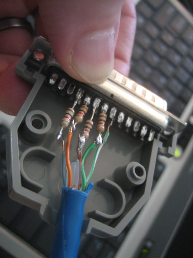
I soldered the 1k resistors directly to the D-sub connector, staggering every other one so that they would be less likely to short out against one another in the shell. I used a bit of cat5 ethernet cabling since I have a lot of it lying around. On the other end I used a DIP IDC (insulation displacement connector) since I’m lazy and I didn’t want to do any more soldering. The cat5 cable is probably at the upper range of wire gauge that will work with an IDC terminator like this, but it worked out. The little pins are probably bent in there though.
Once the cable was finished I tried out avrdude, which I had been using in my homebrew breadboard AVR programmer. It wasn’t able to find the AVR device on the Arduino board, so I was kind of concerned that I messed up somewhere. I got out my meter and double-checked everything and it all looked fine, so I tried out another programmer. Uisp seemed to work initially:
$ sudo uisp -dprog=bsd -dpart=ATmega48
Atmel AVR ATmega48 is found.
However, as I learned later, this command reports that the device is found regardless of whether it is even connected.
I soldered the current-limiting resistors into the headshell. Note that this picture shows 1k resistors, but in the end I dropped these down to 470 ohm resistors to try to get enough current from my parallel port in order to get things working (this didn’t work either, my port is apparently too weak).
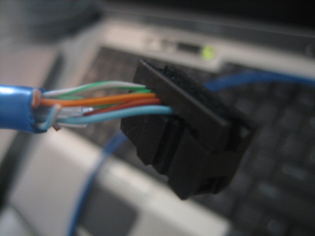
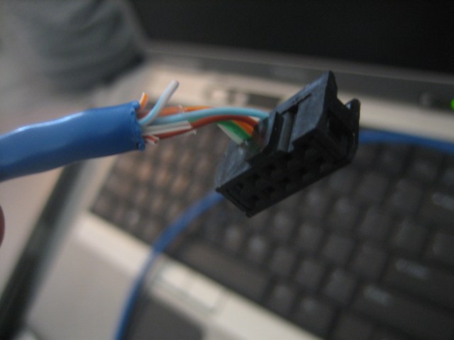
I decided to use an insulation displacement connector for the Arduino side of things. Here you can see different views of that assembly:
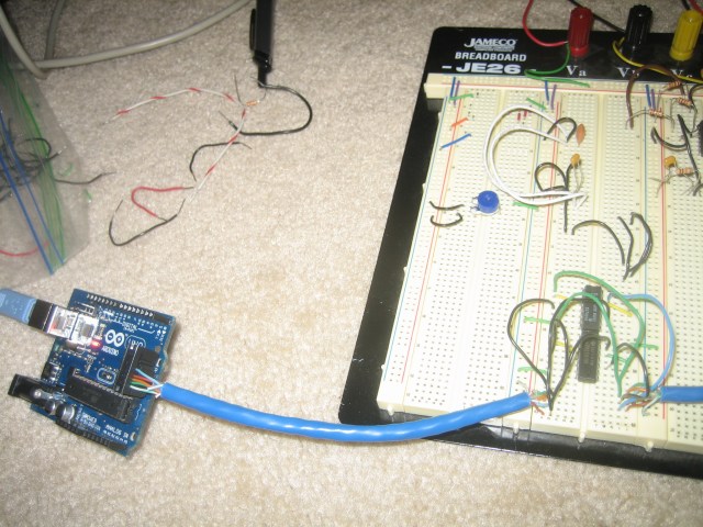
In the end I ended up using a series of inverters as buffers to drive the IO lines between the Arduino and the parallel port. I had a similar set of issues when building my homebrew Arduino circuit. I had 5k resistors there and I was having intermittent issues with the programmer. With the 470 ohm resistors things were working every once in a while, and when they did work I got a different device ID every time. This made me think that I was just not able to sink enough juice to get things working with the AVR device in-circuit on the Arduino board. When the chip was sitting on the breadboard without much else it worked fine. So, I used 2 74ls04 hex inverter ICs for the purpose of sourcing some more power since my parallel port didn’t seem to be up to the task. I used 2 inverters back-to-back in order to form non-inverting buffers. I had a few 74ls07 chips around too, but these are open-collector devices meaning I would have to use a bunch of pull up resistors and I was too lazy to wire that up, so I decided on the hex inverter solution. Since the logic levels were the same (should be 5v, but I didn’t measure my parallel port, and my power supply is actually running at closer to 6v) I didn’t worry too much about not using open-collector devices with pull ups.
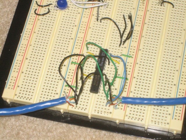
I inserted the buffer circuit inline by cutting my cable in two rather than try to make this a nice finished cable. However, this allows me to make code updates without too much hassle now. I do need to remove the header from the Arduino in order to run the uploaded code (would be nice to have a way to electrically disconnect things. I feel like I should be able to bring reset high to get this to work without disconnecting the cable).
In the midst of this, I thought briefly about abandoning the MIDI firmware so I could just program the Arduino using the USB connection. I might use a serial interface here like the Monome did so that I can implement better bidirectional data support. I want to eventually put LEDs on the pedals of the Kickplate project and in order to do that I need to send data back to the pedals. I thought about using sysex or maybe just sending a MIDI status message with the proper ID for the pedal in question. That design discussion is for another post though.