Audiohackers JamCat design session
At the last audiohackers meetup at Hacker Dojo I was talking with Laura and Kevin about the difficulties that I was having coming up with a way to build a small local network that I was calling a “JamLan”.
I mentioned that I had been thinking about building a simple analog project that would use Cat5 network cable, but I hadn’t come up with the design yet. Somehow the act of explaining what I was thinking and drawing it out roughly on a scrap of paper caused the whole idea to gel.
Here are the rough sketches from that day:
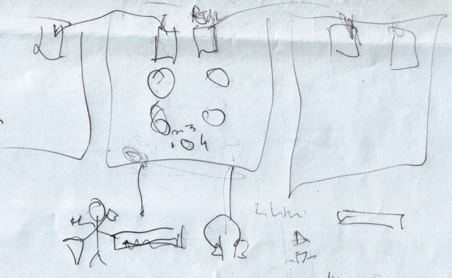 Physical device layout
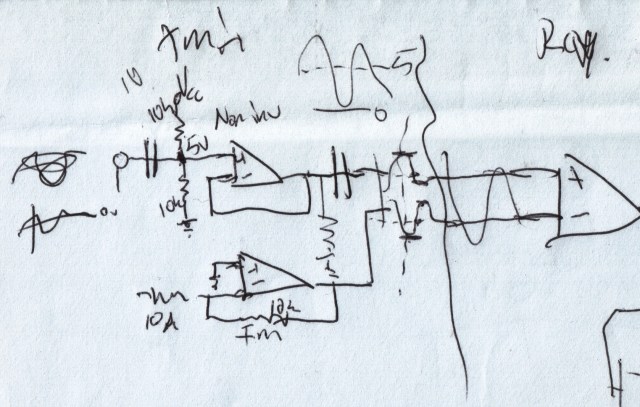
Circuit schematic
After I got home later, that piece of paper was sitting on my desk and I thought I could get that schematic entered into LTSpice and give it a quick test to see if this thing would work at all. I entered in the basic parts and left it for the following day.
After some tweaking and false starts, I had the first working test run, shown in the following screenshot:
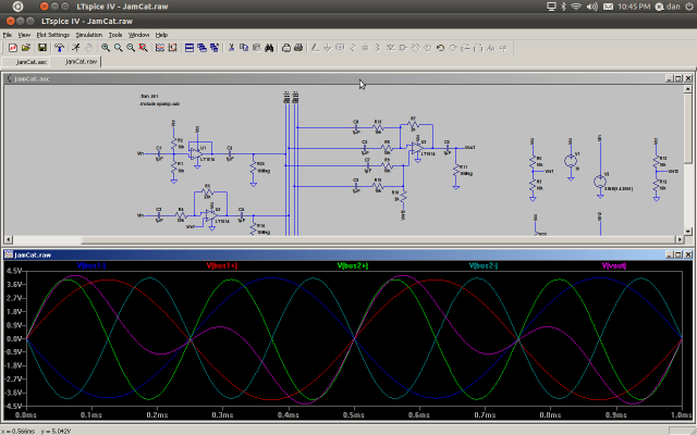
It may not look like much, but those signal traces are showing two “users” (represented by two different sine frequencies) sending signals over a bus to a third party, which is summing them together and playing the result. I’m showing both sides of the differential signal buses so each input waveform is shown with its inverted pair also.
At this point I started thinking about getting some PC boards made up. In hindsight this was a little premature, but I was excited that this circuit was working in simulation at least, and I had verified parts of it on the test bench previously. It was at this point that I realized that I overlooked something important – as designed, I’m going to need dual potentiometers as the volume controls for each channel since they are balanced lines. Oops. This means that the parts will be more expensive and bigger. Bigger parts means that the PC boards will cost more to make.
The alternative would be to redesign the circuit so that each bus would be fed into a separate differential amplifier before being summed. This way the volume control could be inserted between the differential amp and the summing amp, letting us use a single element part.
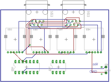
I decided to keep the simpler circuit and try to find a decent part compromise (price/dimensions). I found a nice Alps pot that is stocked by Mouser, and I created a custom package for it in Eagle to do a PCB layout. I just placed the parts and some of the initial PCB traces. This is not the full PCB – not all of the parts are there even. But you can get a peek:
So that’s where things are at the moment. All of this flowed pretty easily from the initial design jam at the meetup. Well it mostly flowed – once I started trying to decide on parts I got bogged down. Somehow it is the hardest part of the design. Once you commit to specific parts and design a board, you can’t easily go for a different part if it doesn’t have the exact same dimensions and pinout unless you want to rework the boards.