Kick Plate MIDI foot pedal build notes
I’m in the middle of getting my prototype Midi foot controller put together so that I can play around with it and practice without worrying about it falling apart in the middle of a session.
I’m mounting the Arduino inside a plastic junction box. Check out the following photo:
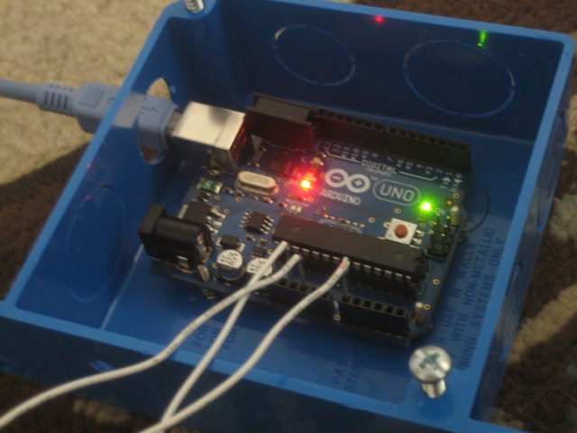
Some issues I ran into with this enclosure were that the walls are a bit thick. This means that my 1/8″ jacks don’t quite fit. I’m either going to have to find some new jacks or get a new enclosure. Not sure which I’m going to do.
This brings me to one of my design decisions which is to use 1/8″ phone plugs and jacks for the connections. I thought about using 1/4″ jacks, which would be more standard among audio equipment. However, these take a lot of room up on the panel so I opted for smaller jacks. I also considered using 2.5mm plugs but these seemed a little bit fragile for something that I’m going to be dragging up on stage. There are some other phone jacks like bantam plugs that would be useful, and I found a 3/16″ jack that would have been pretty cool, but it was tough to find mating plugs. I want to keep this stuff relatively common so I don’t have issues trying to find parts.
I decided to solder the pulldown resistors directly to the jacks, as shown in the following photo:
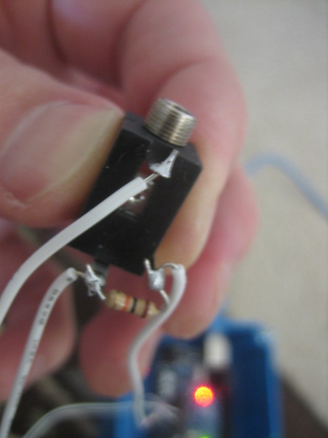
The three connection points are the +5v and ground connections along with the signal output connection. This keeps me from having to mount another board in the enclosure. Ultimately I’d like to create a board for this that doesn’t use the factory Arduino board, but since I need the USB interface I don’t know if this is going to be feasible.
Just a final note on physical fabrication. It’s always harder to get things actually set up in a finished state. I used this drill template from Adafruit. I used some hardware I picked up at Halted to mount the board in the enclosure. In hindsight maybe I could have just used some double-sided tape.