Yamaha CS1x teardown and repair
I had a bad button on my Yamaha CS1x recently and I had to tear it most of the way down in order to fix it, so I took a lot of pictures. I haven’t seen a lot of pics on the Web of this synth, so hopefully these pictures help you out if you need some info on what’s inside the box.
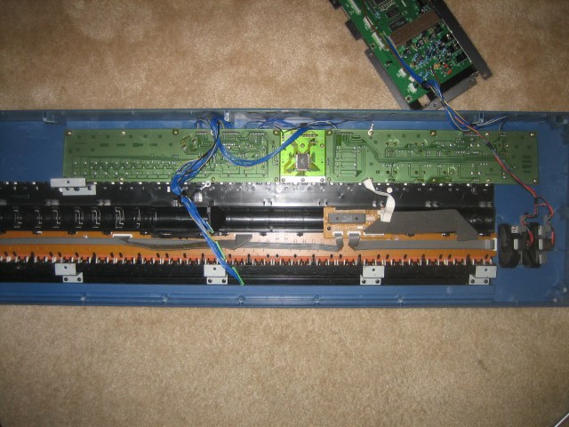
The first step is to remove all of the screws from the underside of the keyboard. Once you remove the bottom, you have pretty much full access to what’s inside. The following pic shows the inside of the chassis from the underside:
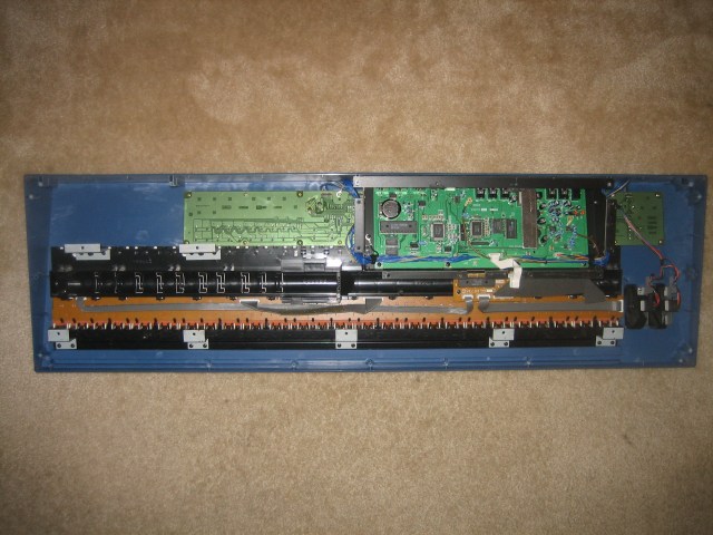
You can see the key assembly along the lower half and the pitch/mod wheels to the right of that. Along the top are the button PCBs with the main logic PCB on top nested in a black folded steel bracket.
I removed the logic board to get at the PCBs underneath:
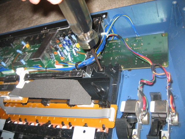
Once the logic board was removed, here is what I could see:
I removed the PCB that contained the button that wasn’t working. Here is what the switches look like:
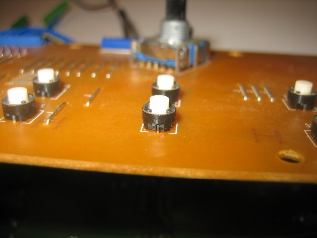
I measured the switch with a caliper to find out how tall it was. Turns out that these are 5 mm tall. So I looked around at DigiKey and grabbed some Panasonic EVQ-11G05R tac switches. DigiKey calls these P8075SCT-ND. I paid about 0.30USD apiece for them.
I desoldered the old switch and put the new one in and buttoned everything up. I tested the old switch in-place to see if it was really bad. It was. The “on” resistance was something like a few hundred ohms. Actually these tac switches all had some kind of resistance in the few ohms, which was kind of concerning, but I didn’t want to replace all of the switches. That would have been a pain, and besides they are working as-is.
So in addition to the repair pics I have some more details on the keyboard and the mod wheel construction:
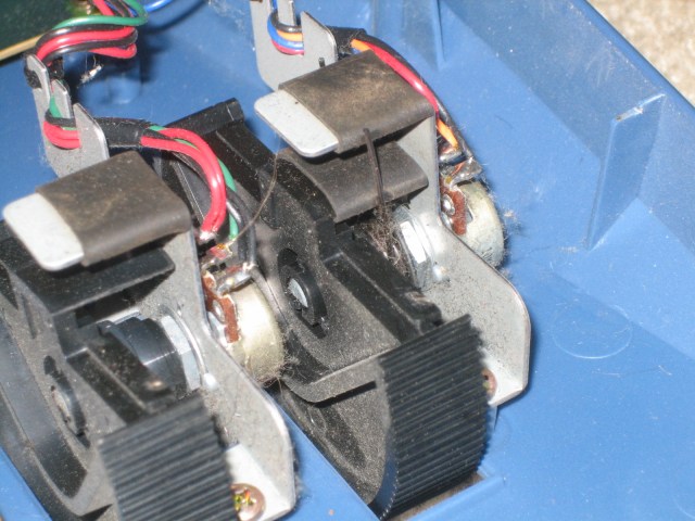
Notice that the mod and pitch wheels are attached to some folded steel brackets that hold the potentiometers. The travel of the wheels is limited by some heatshrink tubing around a tab on the bracket. The pitch wheel has an additional double-ended spring that returns it to the center position. Check out the clever “stacked” spring tabs on the wheel and bracket (towards the right of the pic).
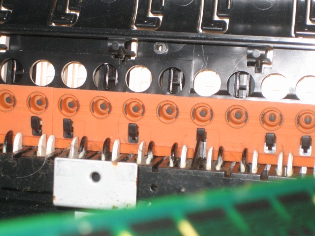
The above pic shows the impregnated rubber contact strip that forms the upper part of the key contacts. Notice that the velocity sensing is done using a perimeter contact on the edges and a separate center “pin” contact that closes afterward. This is a much more compact (and apparently reliable) design than some others that I’ve seen on various keyboards that use two separate contact buttons.
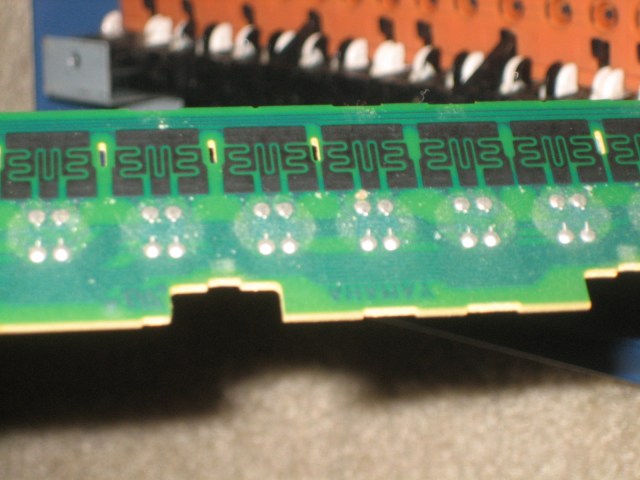
The carbon PCB traces form the lower part of the key contacts. You can see the 3 different contact zones for each key. I’m not sure if the outer zones are connected together or if they are separate. The keyboard is designed to be scanned as a matrix apparently because there are a lot of diodes on the board.
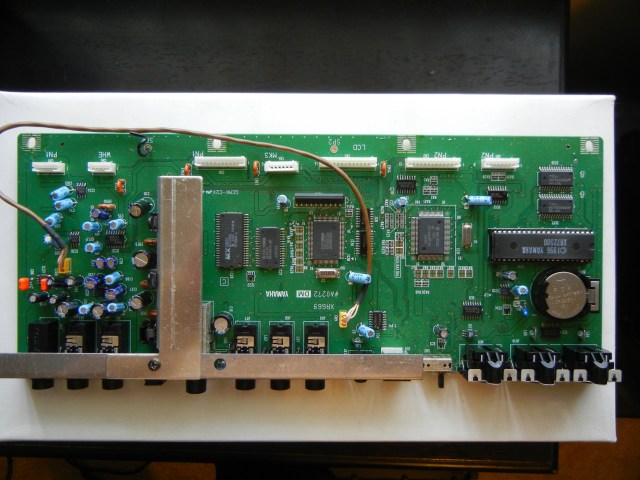
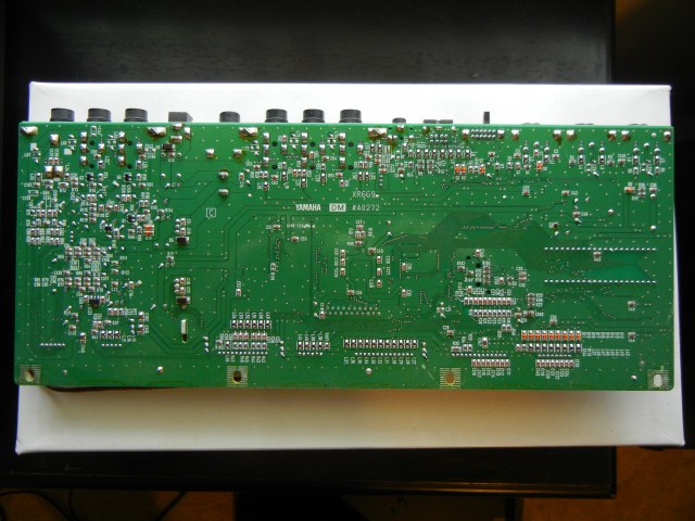
I took a few really high resolution pictures of the main logic board so you can see which components are used: