Duncan convertible amp restoration
I’ve had a 100-watt Seymoure Duncan Convertible amp head in my collection for a few years now. A friend of mine convinced me to pick this amp up on eBay since he had one and loved it. My particular amp was working but in need of some love. Well, I never got around to doing much with it, but now I’m thinking about picking up the project again.
I have plenty of electronics experience, but not with tube electronics. I’m hoping to learn the ins and outs of working with high-voltage tube circuits as part of this endeavor.
Here are a few photos to document the starting point. The chassis has some homegrown fixes and mods applied to it, and my goal is to get it pretty much back to stock.
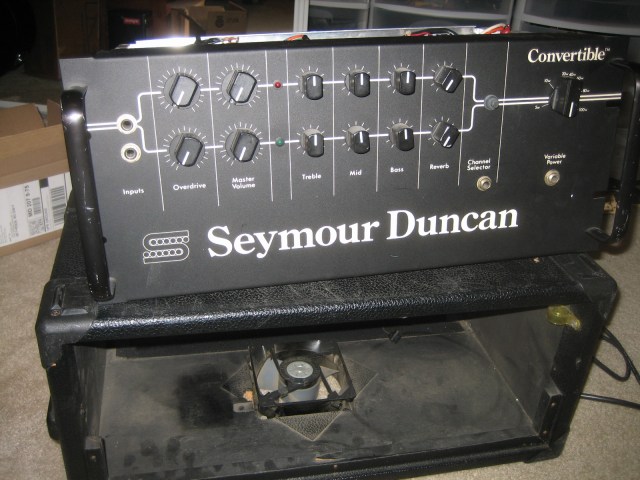
Here is a photo of the front panel with the chassis removed from the cabinet.
Here is the rear of the chassis shown upside-down. Note the size of the power transformer. This thing is a beast. The output tubes and the rectifier have been removed. Note that the power supply caps look pretty beefy as well, and seem to be in good shape.
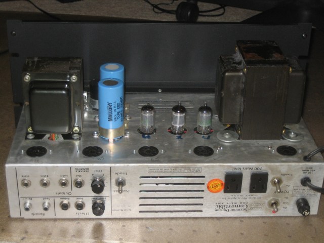
Note that I have connections for a reverb unit, but my cabinet doesn’t show any evidence of there ever being a reverb tank installed. There is no reverb there and I don’t see any old mounting holes that look like they might have been a reverb. Maybe this was an optional thing that could be installed later.
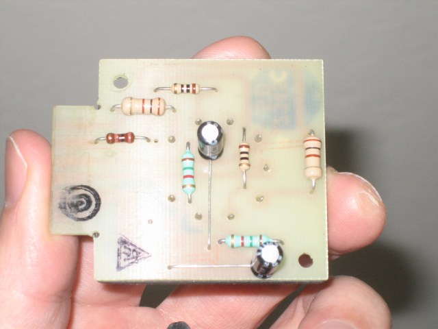
Here is an overview of the circuit board. You can see some hot glue here and some obvious lazy mods and fixes.
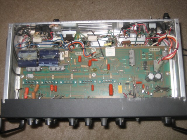
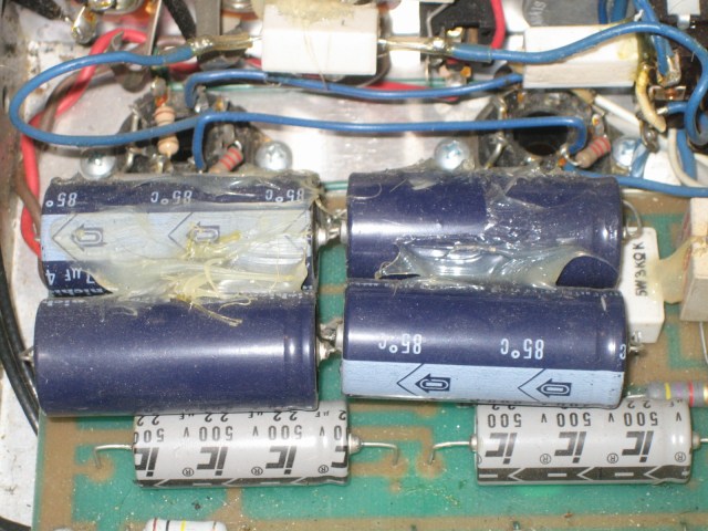
The first thing I noticed was the addition of several additional filter caps tacked on in parallel with the existing caps. I’m not sure which part of the circuit this is. I was under the impression that the main power supply caps were mounted underneath the chassis along with the power transformer. Adding more capacitance here was probably done to reduce some noise or ripple, but I’m not sure where.
In the next picture you can see the card edge connectors that were used to accept the pluggable modules.
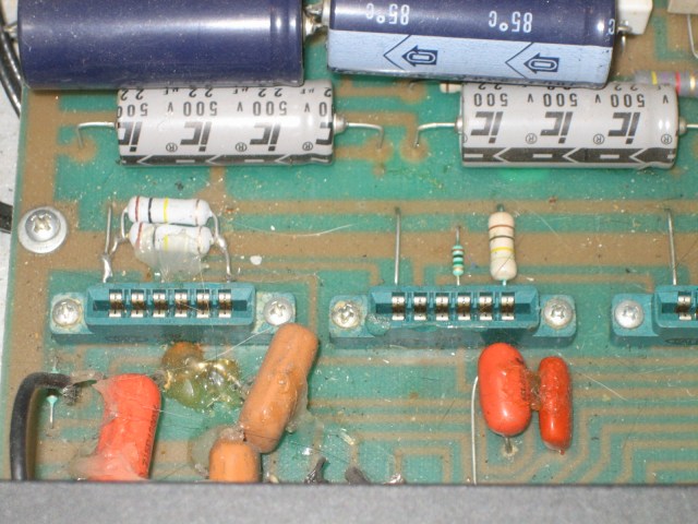
You can also see a hack fix involving two resistors piggy-backed and soldered to the old leads of the previous part. I guess they didn’t have the right value on hand or something, and decided to make use of the fact that R=(R1*R2)/(R1+R2). In this case the equivalent resistance would be 50k ohms.
One of the most interesting parts about this amplifier is the “variable power” feature. This is a circuit that allegedly allows you to drive the output tubes hard without all of the volume. I use a THD Hot plate to soak up power from my big Marshall, so I’m not sure why this isn’t done more often if it is that easy. I’m still studying the schematic to see just how this works.
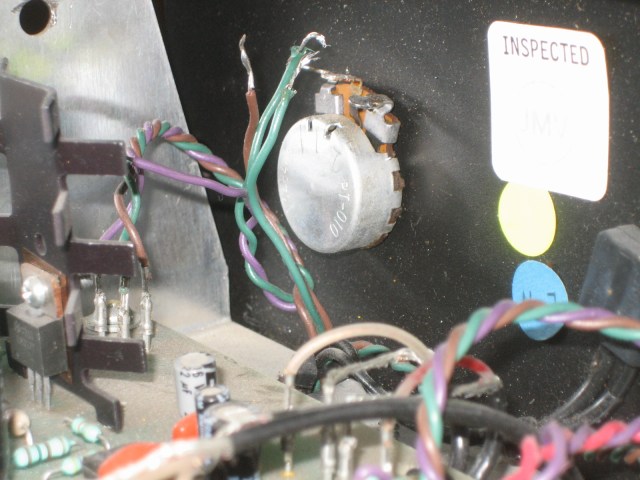
In the above photo you can see the back of the aforementioned variable power control. It looks like the previous owner removed this entirely from the circuit and left the wires hanging there. I’m not sure if I can just hook this back up or if there was a reason that this was done.
Note that there is also a triode/pentode switch on the back, allowing for the output tubes to be used in either mode. This should theoretically allow lower power operation. All-in-all this is a really flexible amplifier.
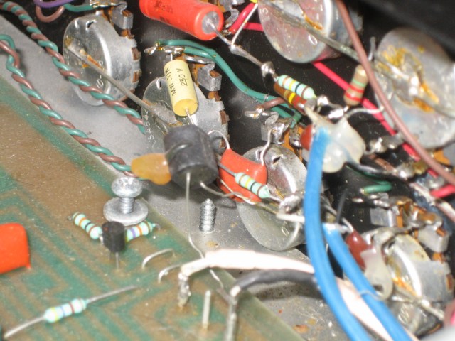
Another questionable bit that I don’t know if it is stock is this ferrite bead soldered between the overdrive knob and the ground rail.
I have 3 of the 5 modules for this amp, which is enough to get one of the channels working. The modules each have one tube socket for a 12AX7 or 12AU7.
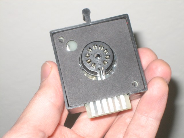
The modules are very simple inside. They consist only of a PC board with card edge connections, a tube and a small assortment of passive components. The following picture is of a “Classic warm tube” module that originally came with the amp as delivered from Seymoure Duncan.
That’s the state of my amp. There are a few other lazy fixes it looks like, but I’ll document those as I repair them. Most of the time it looks like someone replaces resistors and caps by clipping the old ones out and soldering the new ones to the existing component leads. I can only guess that this was done in order to avoid having to remove the board from the chassis, which I’m just going to say is flat-out lazy.
I’m hoping to get this amp back into top form soon.